BEARING LIFE CALCULATION
The working principle of a bearing is to minimize the friction between machine parts that exhibit different behaviors such as two different speeds, opposite directions, or a stationary surface.
Even though it is not perceptible to the naked eye, the rollers or balls inside the bearing undergo micron-level deformation. This deformation is determined by their hardness based on certain speed and load. Typically, rollers and balls applying linear or point pressure distribute the forces on the bearing in the form of friction over a larger area rather than linear or point contact, enabling the rollers to rotate within the bearing. Applying some force to all bearings is necessary for their operation.
There are no specific rules for bearing selection; each designer can use different bearings in the same machines. What matters is that the bearing meets the requirements.
To do this, the following characteristics should be taken into account from catalogs:
- Axial and radial load
- Operating speed
- Operating time
- Bearing life
- Lubrication type
- Choice of sealing elements
- Operating temperature
- Noise level
- Vibration during operation
- Installation method, and more.
In our country, most designers and engineers choose bearings based on inner diameter, outer diameter, and load. This leads to significant mistakes. It is now possible to find these values ready in the catalog of every company, instead of calculating values like load, life, and temperature.
EQUIVALENT DYNAMIC LOAD (P)
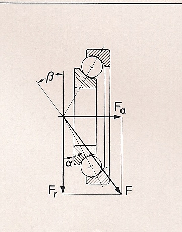
The resultant force formed by radial and axial loads is the main determinant of bearing life.
In the bearing literature, this resultant force is called "Equivalent Dynamic Load (P)," and its formula is P(N) = Fr * cos β + Fa * sin β. Explanation:
The values of sin β and cos β vary depending on the type and size of the bearing and are given in the bearing catalog as X and Y coefficients. Thus:
P = X * Fr + Y * Fa.
If Fa is below a certain magnitude, the second term is considered 0, and the formula becomes P = X * Fr.
Whether Fa will be considered is determined by the "e" coefficient given in the catalog.
If Fa/Fr > e, the formula P = X * Fr + Y * Fa is used.
If Fa/Fr < e, the formula P = X * Fr is used.
Here,
Fr: Radial load (N)
Fa: Axial load (N)
The determined Equivalent Dynamic Load (P) is the main parameter used in calculating the bearing life.
L10 = (C/P)p
L10: Bearing life in millions of revolutions
C: The number of dynamic load cycles in Newtons
P: Dynamic equivalent load in Newtons
p: This value is always 3 for ball bearings and 10/3 for roller bearings.
EQUIVALENT STATIC LOAD (P0)
In life calculations, the "number of dynamic load cycles (C)" is taken from the relevant bearing's table in the catalog. Besides C, the catalog also provides "number of static load cycles (C0)."
The number of static load cycles (C0) is considered in cases where the bearing operates with very low revolutions, undergoes slow oscillatory motions, is stationary under a load, or, most importantly, is exposed to shock loads. In such cases, the performance of the bearing is determined not by fatigue but by permanent deformations caused by the static load. These deformations lead to increased noise, vibration, and friction in the bearings. To ensure the bearing operates without reaching its low-performance limit, in calculations, the static equivalent load P0 (N) is used and calculated as follows:
P0 = X0 * Fr + Y0 * Fa
C0 = s0 * P0, s0 = C0 / P0
C0: The number of static load cycles is taken from the relevant bearing catalog.
s0: Static safety factor
X0, Y0, and s0 are provided in the bearing catalog. The catalog specifies how much the ratio of the static equivalent load should be based on the static safety factor table. (This ratio is less than one for ball bearings unless there are shock loads.) If the calculated s0 value is smaller than the s0 value found in the table, a bearing with a larger C0 value should be selected.